

Mobile Tech support
RD1 ELR
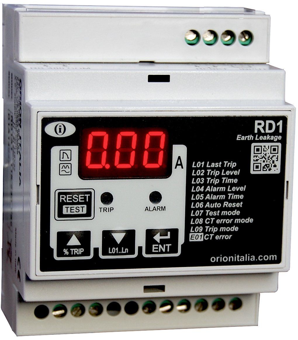

- Menu L01, L02...
L01 Last trip: Displays the current value of the last trip. The value is stored in a non-volatile memory.
L02 Trip Level: Displays the Ampere current value that corresponds to the trip threshold.
L03 Trip Time: Displays the delay time (in seconds) related to the Trip.
L04 Alarm Level: Displays the Ampere current value that corresponds to the Alarm threshold.
L05 Alarm Time: Displays the delay time (in seconds) related to the Alarm.
L06 Auto Reset: Displays if the automatic reset is ON or OFF in case of Trip.
L07 Test mode: Allows to visualize if the test functions of the Alarm and Trip relays is ON or OFF. If OFF, the TEST button will allow to test only the display and the leds.
L08 CT error mode: Displays which output relay will be active in case of connection problems with the toroidal transformer:
ALr = Alarm
TrP = Trip
ALL = both
OFF= no relay
L09 Trip mode: Displays in which mode will be operating the Trip relay:
LA = Latched;
P0.1 impulsive 0,1seconds
P0.2 impulsive 0,2s
P0.3 impulsive 0,3s
P0.4 impulsive 0,4s
P0.5 impulsive 0,5s
P0.6 impulsive 0,6s
P0.7 impulsive 0,7s
P0.8 impulsive 0,8s
P0.9 impulsive 0,9s
- Alarm E01 CT Error
E01 CT Error: The current transformer is not connected to the earth leakage relay or there isn’t a good connection between the two.
- Tech Support Documents
Basic usage video
Setpoints video

- Menu L01, L02...
L01 Mostra il valore di corrente nell’istante dello sgancio (Trip) relativo all’ultimo intervento. Il valore viene memorizzato in memoria non volatile.
L02 Mostra il livello di corrente in Ampere
corrispondente alla soglia di intervento (Trip)
L03 Trip Time: Mostra il ritardo all’intervento, espresso in secondi, relativo alla soglia di intervento (Trip)
L04 Alarm Level: Mostra il livello di corrente in Ampere corrispondente alla soglia di Allarme (Alarm)
L05 Alarm Time: Mostra il ritardo all’intervento, espresso in secondi, relativo alla soglia di Allarme (Alarm)
L06 Auto Reset: Mostra se è abilitato (ON) o disabilitato (OFF) il reset automatico in caso di Trip.
L07 Test mode: Permette di visualizzare se è abilitata (ON) o disabilitata (OFF) la funzione test dei relè Alarm e Trip. Se disabilitata, il tasto Test consentirà solo di testare il display e i led.
L08 CT error mode: Mostra quale relè di uscita dovrà operare in caso di guasto al collegamento con il trasformatore toroidale:
ALr = Rele Alarm
TrP = Rele Trip
ALL = Entrambi
OFF= nessun rele
L09 Trip mode: Visualizza la modalità con la quale opererà il relè di Trip:
LA = Ritenuto (Attivo fino a reset)
P0.1 impulsivo, Durata impulto 0,1 secondi
P0.2 impulsivo 0,2s
P0.3 impulsivo 0,3s
P0.4 impulsivo 0,4s
P0.5 impulsivo 0,5s
P0.6 impulsivo 0,6s
P0.7 impulsivo 0,7s
P0.8 impulsivo 0,8s
P0.9 impulsivo 0,9s
- Allarme E01 CT Error
E01 Errore CT: il trasformatore di corrente non è collegato al relè di dispersione a terra o non esiste una buona connessione tra i due.
- Documentazione Tecnica